
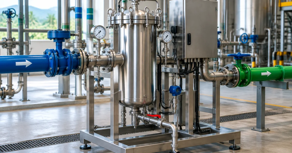
How to Specify, Size, and Integrate a Self Cleaning Filtration System for Continuous Industrial Processes
In continuous industrial processes, filtration issues rarely fail gracefully. A small mismatch—wrong micron rating, insufficient differential pressure (ΔP) margin, an undersized flush line, or unclear control logic—can lead to unstable flow, frequent cleaning cycles, quality excursions, or shutdowns.
This tutorial shows how to specify, size, and integrate a self-cleaning filtration system so it behaves like a dependable, always-on asset. If you are evaluating an industrial filtration equipment supplier for a project in Malaysia (process water, utilities, chemical lines, food & beverage, or industrial wastewater), use these steps to tighten your RFQ and design review.
Step 1: Define the duty—what “continuous” means for your line
Before selecting a model, define the operating envelope and what the process can tolerate during cleaning.
- Service fluid: process/cooling water, CIP return, solvents, syrup/brine, chemical feed, boiler make-up pre-treatment, etc.
- Flow profile: normal/min/peak flow; steady vs. variable (VFD pumps, batch transfers).
- Solids loading: solids type (sand, rust, carbon fines, fibers, biological matter) and whether loading is steady or episodic.
- Required filtrate quality: what you are protecting (nozzles, heat exchangers, spray balls, RO/UF membranes, product-contact surfaces).
- Allowable ΔP: maximum pressure drop the process can accept without starving downstream equipment.
- Continuity requirement: is a small transient during cleaning acceptable, or must outlet pressure/flow remain essentially constant?
Practical note: Many designs “clean while filtering,” but valve actuation and flush diversion can still cause a brief ΔP/flow disturbance. Decide early whether you can manage that with control sequencing or a buffer volume.
Step 2: Select the filtration principle and cleaning method for the contaminant type
“Self-cleaning filtration system” spans multiple mechanisms (screen/disc media, backwash, suction scanners, motorized brush/scraper designs). Selection should be driven by how the solids behave, not just the micron rating.
Match the mechanism to solids behavior
- Hard particles (sand, scale, rust): screen-based systems typically perform well when cleaning can dislodge the layer from the surface.
- Fibrous/soft solids (pulp, fibers, algae): confirm the media geometry and cleaning action are resistant to blinding; consider upstream strainers if needed.
- Sticky/greasy solids: verify the cleaning method can detach the cake in real conditions; chemistry/temperature and upstream process changes may be decisive.
- Very fine particles (e.g., carbon fines): a self-cleaning screen may be a bulk-removal stage, not final polishing.
Decide: single unit vs. staged filtration
For true “continuous” performance under variable solids loading, staged filtration is often more stable:
- Stage 1 (bulk removal): self-cleaning filter removes most suspended solids.
- Stage 2 (polishing): cartridge or bag filter tightens final quality when required (product quality or membrane protection).
This reduces nuisance clean cycles and makes outlet quality less sensitive to solids slugs.
Step 3: Size the system—flow, micron rating, ΔP window, and cleaning hydraulics
Continuous operation is won or lost in sizing. Avoid “line-size-only” selection; base the specification on hydraulics, allowable ΔP, and cleaning performance at worst-case conditions.
3.1 Establish the design flow and turndown
- Normal/peak flow and the minimum stable flow (if variable).
- Available upstream pressure and the downstream minimum pressure requirement.
- Any known expansion factor (e.g., an additional production line).
Tip: If the process often runs far below peak, ask how cleaning initiates at low velocity. Some designs need sufficient shear/velocity; controls may require minimum-flow permissives or different setpoints at low flow.
3.2 Choose a practical filtration grade (micron rating)
Select a grade that protects the most sensitive downstream item without forcing constant cleaning. Over-specifying (too fine) often converts “no consumables” into “frequent backwash.”
- Protecting spray nozzles/heat exchangers typically allows a coarser grade than protecting membranes.
- If you truly need fine removal, keep the self-cleaning stage as bulk protection and add a downstream polishing stage.
3.3 Define the ΔP operating window (baseline, clean trigger, alarm, trip)
Write ΔP behavior into the specification so operations are predictable:
- Clean ΔP: baseline at design flow with a clean element/screen.
- Cleaning-start ΔP: setpoint to initiate an automatic cleaning cycle.
- High ΔP alarm: indicates cleaning is ineffective (blinding, wrong solids type, blocked flush line, insufficient differential for backwash).
- Trip/shutdown ΔP (optional): use only when downstream risk is severe (e.g., cavitation risk, membrane damage).
Ask the supplier to propose initial setpoints based on their pressure-drop curves, then validate and tune during commissioning with actual flow/temperature/solids.
3.4 Verify cleaning flow requirements (backwash/flush line sizing)
Cleaning performance depends on the flush path. Integration errors here are a top cause of “ΔP doesn’t recover.” Confirm:
- Flush flow and duration per cycle.
- Flush destination: open drain, recovery tank, wastewater pit, or a suitable return point.
- Maximum allowable backpressure on the flush line; avoid long restrictive runs, small shared headers, and excessive elbows.
- Isolation and maintainability: valves/arrangements that allow safe servicing without shutting down an entire plant header where possible.
If you backwash to a pressurized return, verify the required differential exists in all scenarios (low upstream pressure, high downstream pressure, low flow).
3.5 Materials and compatibility
Confirm wetted materials and elastomers against the service fluid, temperature, and any cleaning/CIP chemicals. Specify metallurgy and gasket requirements explicitly for chemical duties.
Step 4: Specify the integration package—piping, valves, instrumentation, and controls
A self-cleaning unit is a system, not just a vessel. Your RFQ should cover how it integrates mechanically and electrically.
4.1 Piping arrangement and bypass philosophy
- No bypass: maximum protection (all flow filtered). Plan redundancy or maintenance windows.
- Manual bypass: maintains flow during maintenance but risks unfiltered operation; use lockable valves and clear procedures.
- Duty/standby (N+1): two filters in parallel with switchover; common for high-availability utilities.
Also confirm preferred orientation (drainage, venting, access) and any straight-length requirements upstream/downstream.
4.2 Instrumentation to include (minimum practical set)
- ΔP measurement: ΔP transmitter or two pressure transmitters with suitable range margin.
- Flow indication: process flow and, where practical, flush flow to support troubleshooting and tuning.
- Local gauges: quick validation during start-up/maintenance.
- Valve position feedback: for automated flush valves to confirm actuation.
State your preferred signal standards and integration method (e.g., 4–20 mA, dry contacts, networked I/O) to align with plant practice.
4.3 Control logic: cleaning trigger and failure handling
- ΔP-based: most common; best when solids loading varies.
- Time-based: acceptable only when loading is predictable; otherwise can under- or over-clean.
- Hybrid: periodic “keep-alive” cleaning with ΔP override.
Define failure handling in the RFQ:
- What happens if ΔP stays high after X cycles?
- What alarms go to DCS/SCADA?
- Automatic switch to standby filter (if installed)?
- Permissives (e.g., minimum flow) before allowing a cycle?
4.4 RFQ essentials: what to request from your supplier
- GA drawing (connections, weights, maintenance clearances)
- P&ID (skid boundary and recommended tie-ins)
- Instrument list and I/O list (signals, alarms, interlocks)
- Utilities (power, instrument air if needed, drain/flush requirements)
- O&M manual and recommended spares
- Commissioning checklist and suggested acceptance tests
Step 5: Use a decision table to lock the specification before you buy
Use the table below to compare proposals and expose common integration risks before purchase.
| Specification item | Define | Verify with supplier |
|---|---|---|
| Design flow & turndown | Normal/peak/min flow; variability | Rated flow, minimum flow for effective cleaning, pressure-drop curve |
| Filtration grade | Micron rating tied to downstream protection | Recommended media/screen and expected cleaning frequency range |
| ΔP window | Clean ΔP, start-clean, alarm, optional trip | Suggested setpoints and effect of flow/viscosity |
| Backwash/flush hydraulics | Flush flow/duration, destination, allowable backpressure | Required differential for cleaning and flush line sizing guidance |
| Materials & seals | Wetted metallurgy, elastomers, temperature/chemistry limits | Compatibility confirmation for service fluid and cleaning chemicals |
| Controls & integration | Trigger logic, permissives, alarms, I/O/comms | Control narrative, I/O list, safe states and manual overrides |
Step 6: Commissioning and performance verification (what “good” looks like)
Commissioning is where you confirm assumptions and tune the system to real solids loading.
6.1 Pre-start checks
- Confirm flow direction, venting, and drainage.
- Stroke-test automated valves and verify position feedback.
- Validate pressure/ΔP instruments at zero/low flow.
- Confirm the flush destination can accept flow without flooding or pressurizing.
6.2 Start-up tuning steps
- Record baseline: log clean ΔP at stable flow.
- Run a manual cleaning cycle: confirm ΔP recovery and correct flush path/duration.
- Set initial ΔP trigger: start conservatively; adjust to avoid over-cleaning while maintaining protection.
- Test edge cases: observe cleaning at low and peak flow (as feasible).
6.3 Common integration problems and quick diagnostics
- ΔP does not return to baseline: check flush line backpressure and differential first; then assess blinding/incorrect screen grade.
- Frequent cleaning with little solids: ΔP trigger too low, actual flow higher than assumed, or fluid viscosity/temperature differs.
- Downstream pressure dips during cleaning: flush diversion too aggressive or sequencing not aligned with pumps/VFDs; consider buffering or revised logic.
- Downstream fouling persists: grade too coarse or deformable solids pass; consider staged filtration or alternate media.
Conclusion: Build the specification around hydraulics and integration—not just the vessel
A self-cleaning filtration system can support continuous industrial processes when you define the duty, size it around a realistic ΔP window, and treat cleaning hydraulics, instrumentation, and controls as part of one integrated system. Use the decision table to finalize requirements, then request GA/P&ID, I/O lists, and a commissioning checklist with your RFQ to reduce site surprises and speed start-up.
Useful next reads
Frequently Asked Questions
How do I choose the right micron rating for a self-cleaning filter in a continuous process?
Start from the most sensitive downstream item (nozzles, heat exchanger passages, membranes) and choose a grade that protects it without causing constant cleaning. If the required grade is very fine, consider a two-stage design: self-cleaning filtration for bulk solids removal, followed by a cartridge or bag polishing stage.
What differential pressure (ΔP) setpoints should I specify for automatic cleaning?
Define four values: clean ΔP at design flow, a cleaning-start ΔP, a high ΔP alarm, and (only if necessary) a trip ΔP. Your supplier should propose initial setpoints based on the filter’s pressure drop curve, then you tune them during commissioning using actual flow, temperature, and solids loading.
Where should the backwash/flush line discharge to avoid cleaning failures?
Discharge to a destination that can accept the flush flow without creating backpressure—commonly an open drain, sump, or dedicated recovery tank. Avoid small shared headers or long restrictive pipe runs. Excess backpressure on the flush line is a common reason ΔP does not recover after a cleaning cycle.
Can a self-cleaning filtration system replace cartridge or bag filters completely?
Sometimes, yes—when the goal is bulk solids removal and the downstream equipment can tolerate the filtrate quality. If you need very fine particulate control or consistent polishing, a self-cleaning filter is often better as a first stage, with cartridges or bags downstream to meet tighter filtration grades.
What should an EPC contractor ask an industrial filtration equipment supplier to include in the RFQ package?
Request a GA drawing, skid P&ID, instrument and I/O lists, utility requirements (power, drain/flush), control narrative (cleaning triggers, alarms, permissives), and recommended spares. These documents reduce integration risk and make it easier to align piping, electrical, and SCADA/DCS requirements before fabrication.
Need a self-cleaning filtration system sized for your continuous process?
Recalyx designs and manufactures self-cleaning filtration systems, stainless steel filter housings, cartridges, bag filters, UV disinfection systems, and flow measurement solutions—supported by in-house engineering and end-to-end technical support. If you share your flow range, contaminant type, operating pressure/temperature, and flush destination constraints, our team can help you specify the right filtration grade, ΔP setpoints, and integration details for a smoother commissioning.